Revision 2.2
Pictures “says” more than 1000 words …
Note: this is a Zero-Revision release and therefore has some flaws (sorry for that). If you follow my advice it should be no problem to deal with that.
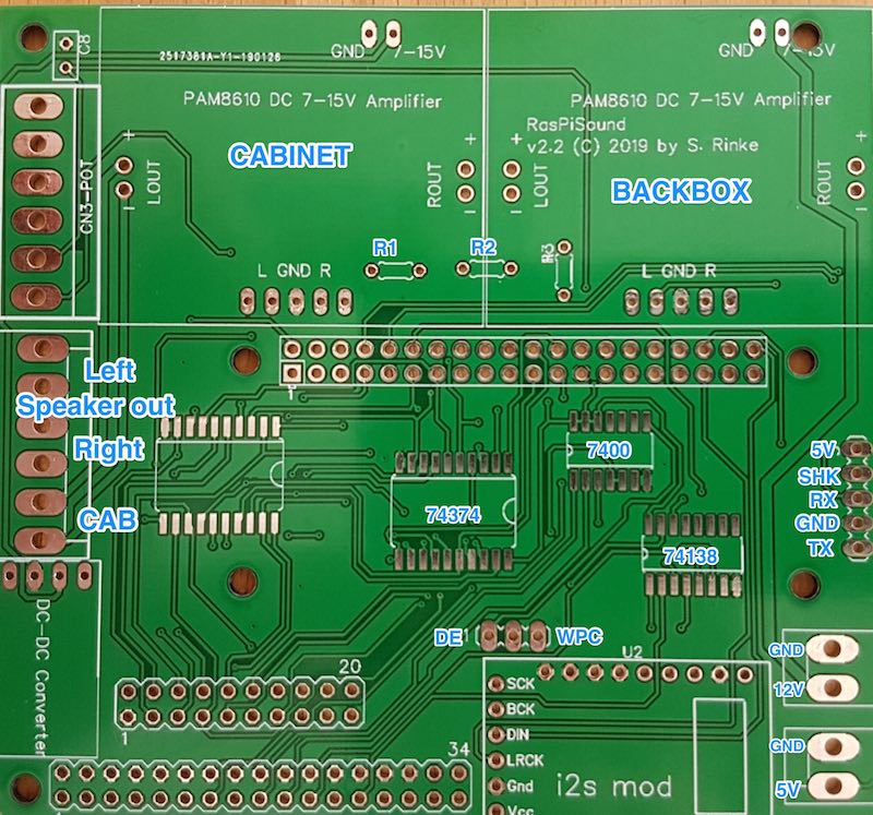
- Be aware of the orientation of the big smd piece LCX374. Its pin 1 is on upper right.
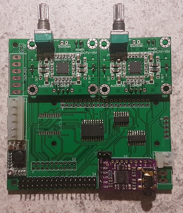
- The i2s module (purple) does not fit exactly, first solder the 6 pins on the left, then connect the two output (L and R) with a small piece of wire. This will be corrected in the new revision.
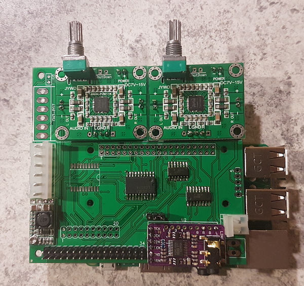
- For Pi3 underneath mounting there is a chance that the Pi’s ethernet connector touches the shield and maybe causing a short even so there should be enough solder resist to prevent that. To be save, just put something in between and fix it with some glue.
- If you like to use a PiZero the Pi connector on the shield must be mounted on the top.
Power supply is only on the 12V in connector. The Pi itself is driven by the onboard dc-dc step down converter, that produces 5V. The 5V connector bottom right can either be used as an 5V outlet (converter makes up to 3A) or simply don’t populate it at all.
As an alternative you can leave out the step down converter and instead provide 5V via the connector bottom right.