Just go forward and buy a ready to use image at my shop.
After downloading the image decompress it using 7zip or xz and write the image to a 16GB micro sd card using etcher or Win32DiskImage (or similar tool).
Startup
Put sd card into Pi3 slot, connect a HDMI display and power it up 🙂
Connections
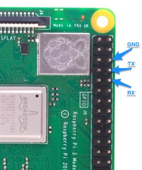
serial media server uses (in default configuration) the builtin hardware UART of the pi. It is exposed at pins 6, 8 and 10
The comm port configuration is 57600 8N1.
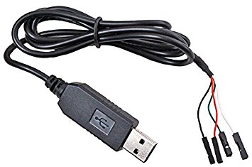
So the easiest test would be get some USB to TTL 3.3V serial cable like this and then connect via putty (or similar) to send some commands to serial media server.
Commands
Commands always consist of 2 bytes. The two bytes represent a 16 Bit hex number or in other word 1. byte * 256 + 2. byte gives you the final number. If you connect via terminal program bytes are typically send in ascii code, which means if you type „00“ (two times zero) this will result in 48 (ascii for zero) * 256 + 48 = 12336. So 12336 is the resulting „command“.
serial media server is simply looking for a file like 12336.jpg or png to show. Or 12336.mp4 to play.
Media files
sd card is splitted in 2 partitions:
windows readable data partition
linux partition hosting serial media server binaries
media files all got to windows partition „data“ directory. So to copy media to the server just plug the sd card into your computer before starting media server and copy your media to the data directory. In order to get something played follow the naming convention mentioned above.
Using together with TILT!Audio*
Starting with version 1.17 of TILT!Audio* you can add a control file called serial.txt to every sound effect directory.
serial.txt file typically just contains one line mentioning one number which is the serial command for the media server. So in order to play this 12336.mp4 I used in the example above, just type 12336 in the serial.txt file and you’re done.
You can also use more than just one command in serial.txt by just adding more numbers separated by space like „12336 12337“ this would send either 12336 or 12337 commands to the media server choosen by random.
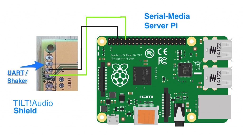
Connecting TILT!Audio Shield to server
As the UART connection is effectively unidirectional (TILT!Audio* sends, server listens) you only need two wires to connect the two like this
Together with a friend of mine we planned for quite some time to recreate a mod for the creature from the black lagoon CFTBL. The hologram always looses in structure so over time, the optical effect is gone.
There couple of mods in the past, most noteworthy the one from PinballMike. As creator of TILT!Audio* and Co-Author of pin2dmd, there was a long lasting wish to control additional hardware based on a serial control signal coming from pin2dmd or RasPiSound, which got its first application now in this CTFBL mod.
The incredients are:
TILT!Audio* for CTFBL with latest firmware version 1.16 or newer
Serial-Media-Server
TILT!Audio* you may know already is a sound card replacement for data east or wpc machines based on a raspberry pi is introduced here:
Serial-Media-Server is a relatively simple project also based on a pi3 with raspbian stretch lite, omxplayer and a python server. The sound hardware communicated with serial-media-server via a serial line at 57600 baud 8N1.
Combining the two requires two serial wires and some software configuration. The basic steps are always:
Define a serial command for a sound effect, that is send out each time the sound is triggered.
Define a media file, that serial media server should play / show on a specific command.
How is this done?
Serial command are just numbers. To send out a command with a sound effect just create a file „serial.txt“ in the sound effect directory and write a number in the first line.
On the data directory of the serial media server create a file like <number>.mp4 or <number>.jpg and the file gets played / shown.
Sounds easy? It is easy.
For serial-media-server you can get further information on github. There is even a ready to use image for serial-media-server available here.
How will it look like?
A friend of mine did a demo with his CTFBL machine:
Also note that there’s all playback content for CFTBL included, if you choose the full CFTBL-serial-media image. See here.
TILT!Audio* is a DIY project but I sell kits to build one in my shop. Depending on the feedback for the new CFTBL mod, I may also offer kits for the that (display mounting basically). Software is already provided as mentioned above.
Partlist
For RasPiSound:
1* power supply 12V Mean Well RD-65A (or RD-85A) combined one with 12V / 5V
After quite some time (TILT!Audio* started in January 2017) I finally managed to get WPC sound running. The main difference to the first approach with dataeast is the different bus speed, that is used in WPC systems. This is because in WPC systems the bus between the main cpu and the sound subsystem is shared between the dmd controller and the sound card. This requires a higher bus speed and additional addressing wires.
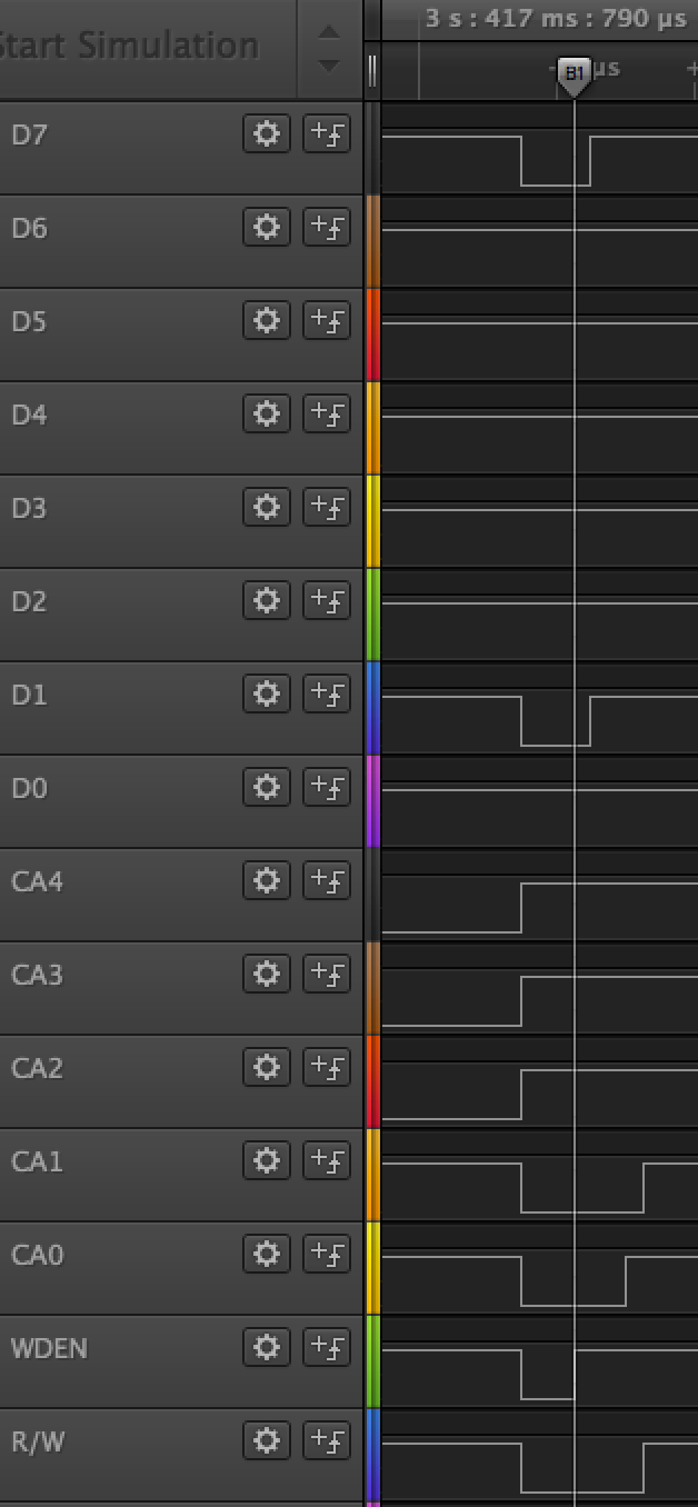
My first try was to translate all the control wires 5 address lines, RW and WDEN directly to GPIO of the Pi. The idea was to simply do the address decoding in software within the interrupt service routine.
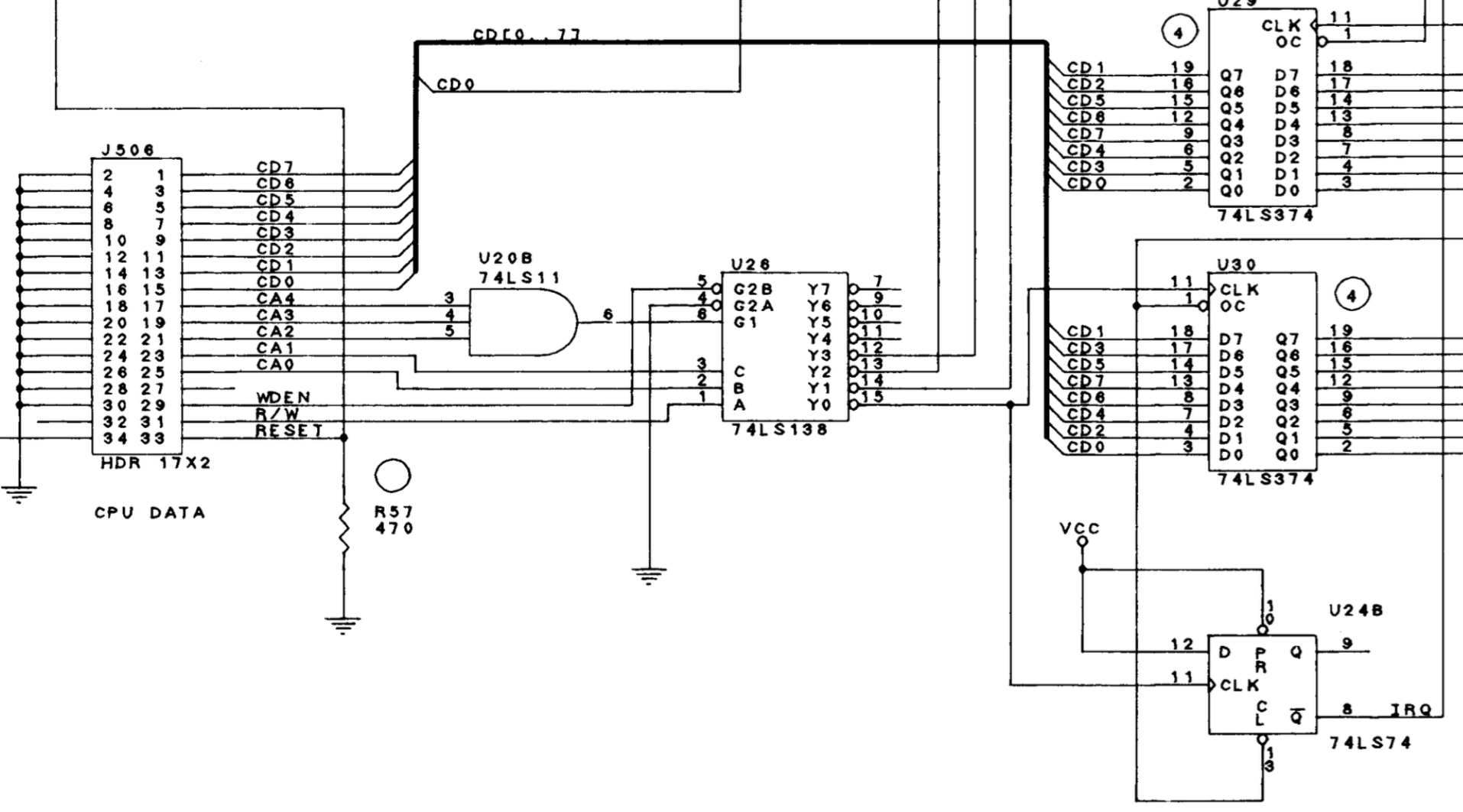
Looking at the output of the logic analyser and on the schematics you can see that writing to the 374 buffer requires CA0 and CA1 to be low, while CA2-4 need to be high. The CLK for the 374 buffer will go high exactly when WDEN goes high while RW is still on low.
Exactly this transition can be seen on the right.
The solution finally was to do the address decoding in hardware. This has reduced the frequency of interrupts dramatically. Effectively an interrupts only occurs, if a command byte is transferred to the sound card. The fact that wpc to some extend uses multi byte commands can be handled by the software. Sequences of command bytes are send with a 1ms delay between bytes so that the maximum interrupt frequency is around 1kHz.
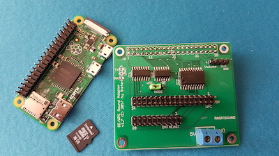
Another improvement as I need to design a new adapter shield anyways was to consolidate the level shifter and the buffering of the sound data byte in a single chip that can be operated at 3v3 and has 5v tolerant inputs. Additionally I make use of the new Raspberry Pi Zero which has enough power and memory for the sound generation.
This results in a smaller and also cheaper design for wpc and with some smaller changes in the software the same approach could be used for dataeast as well.
As soon as the final shield is ready and tested, I will provide PCBs and kits in my shop at //go-dmd.de/shop.
Finally you can see the first working demo here:
Schematics for shield:
Update: today the PCBs arrived from manufacturer. Works like a charm. Also easy to assemble if you have some soldering experience, if not order a ready to use set here.
My latest project is about sound. Inspired from a small project from Christoph found here I was willing to try that with my Jurassic Park machine as well. Raspberry Pi B+ was already lying around so first test run was really fast.
I assembled a small strip board with thread wires to connect the pinball machines inputs via a level shifter to the raspberry pi. I am using active level shifters 74HC4050 that has 6 non inverting buffers in a DIL 16 case, two of them are needed. I also designed a real PCB (see gerber / eagle files in the project directory on gitlab).
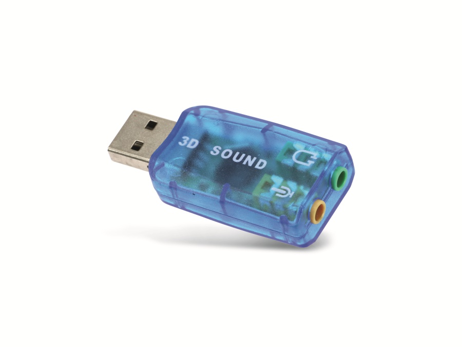
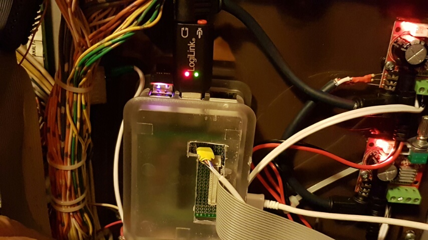
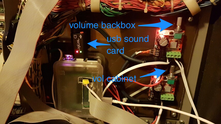
To get a better sound quality I also used a USB sound card together with the PI, because there are many complaints about the poor quality of build in sound. Not sure if this is still true with an actual Rasp Pi 3, but you can get such a sound card for only 4€ or so.
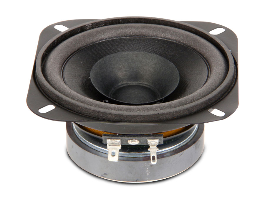
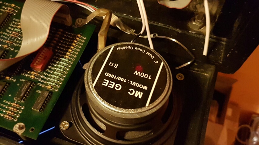
In order to get real powerful audio we need to have amplifiers and better speakers at least in the backbox panel. For the speaker I used also rather cheap ones from McGee, that actually sounds much better than the original ones, although you can get one for about 5€ each (see parts list at the end of the page).
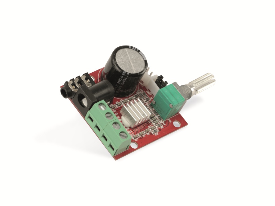
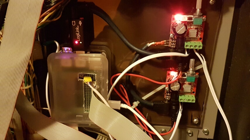
As amplifier I’m using two modules from here, each has 2x10W one for stereo backbox sound and one additional channel for cabinet speaker. It has a volume control so you can level volume for backbox and cabinet separately.
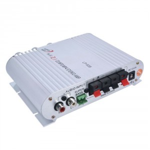
As an alternative you could also use some of these 2.1 channel car amplifiers like this.
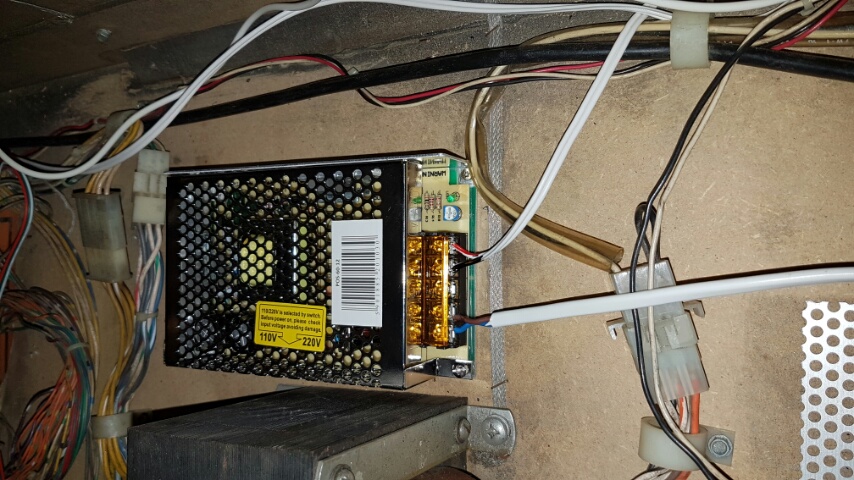
To avoid noise or any kind of disturbance I’m using a separate PSU 12V/5A only for the amplifiers. Connections between sound card output and amplifiers input uses shielded cables, also to minimize noise. For the backbox channel I simple combine the two stereo channels (left and right) to one with two resistors.
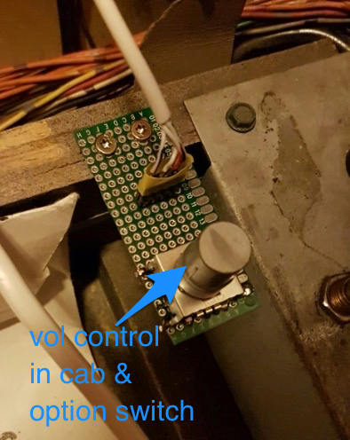
To control the new sound system in a pinball machine I also connected a rotary encoder with click function to the raspberry pi. It can be installed near to classic volume controller inside the cabinet, so its easy to reach when coin door is open. The click function is used for switching between different sound sets.
In order to get good sounds or good quality we need to have good sounding mp3 or wav files to play. The easiest way to get that is either ripp the sounds from the game roms with a tool called „m1“ or simply download a complete sound set from the internet.
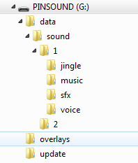
The software on the PI supports the file structure with four subdirectories „jingle“, „sfx“, „voice“ and „music“. Each of these directories containing again another directory that has the sound number encoded in the directory name like „XXXXXX-*“, where XXXXXX is the 6 digit sound number. Just extract a sound set to the sd card and start the „despi“ sound controller with a parameter pointing to the containing directory.
The software uses SDL / SDL_Mixer to produce background music and sound effects and despite it can read many different formats, it is best to use the same format we are going to output from the PI. In our case this means simply use WAV files 16 bit, 44100 Hz. Any other format will converted to this format internally on load time anyways, so effectively this only slows down to load or starting time.
If the PI has enough ram (normally the case) it is best to preload all the sound effects before starting. This avoids latency when the sound gets played. This is controlled with the „-p“ option at startup. If you place an empty file named „dontpreload“ in any of the soundsets directories, sounds of that directory will skipped when preloading. This can be used for sounds that normally never or very rarely gets played, especially when ram is short.
As the program itself has no UI of course, it uses some build in sounds to give status feedback. These sounds are located in the sounds directory and can easily customized.
Wire protocol
The protocol between cpu and sound board is rather simple: there is a 8 bit data word and strobe for communicating from cpu to sound, and a busy and sst0 the other way round.
Data is received when strobe goes low and is acknowledged with a short low pulse on busy. While music is playing sst0 is also pulsed low every 250ms. This is implemented in pincom.c / despi.c and works really simple.
Christoph did a nice job and reverse engineer this with a few logic analyser recordings:
Software
The software is based on Arch Linux but raspbian works as well. If you not able / not willing to compile the source for yourself, I can also offer a complete image for the PI (linux and despi included). Only thing to add is of course: sounds!
Assembling
PSU for sound amplifiersRaspberry pi (within the case) and pinball connectorseverything mounted on a framenew backbox speakersrotary encoder in the cab front for vol control
There is also an sdcard image ready to use: you can simply „buy“ it in my shop: //go-dmd.de/shop/ (its a 0€ product).
The image is for a 16GB sdcard and has two partitions:
Boot- and data partition (fat32)
Linux partition (ext4)
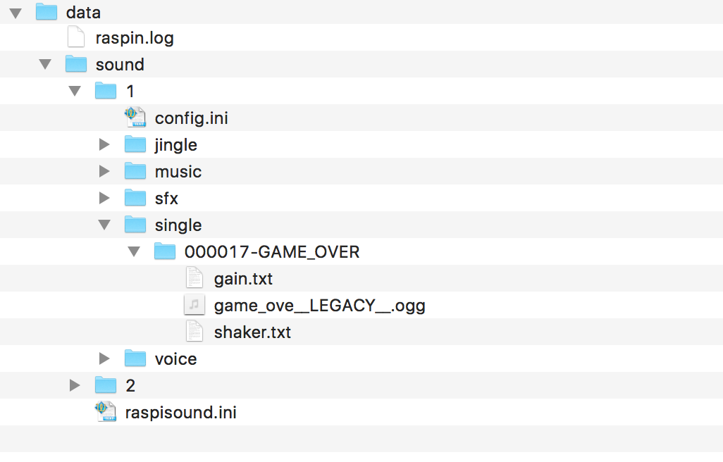
Boot partition contains a data/sound directory where the sound sets must be placed. Complete directory structure looks like this:
To configure a usb sound card instead of the build in sound, simply put a file „use-usb.txt“ into the data directory.
The image is tested with a PI3 but should also work with older versions. Base image is a arch linux, with a few tools installed. There’s two users ‚pi‘ and ‚root‘ it you like to connect to the pi via ssh. (password is the same as username).
The sound program itself is installed as a system level service controlled by systemctl / systemd. It is called ‚pinsound‘, so calling ’systemctl status pinsound‘ should produce some status information.
If everything is correctly setup the starting sound system should produce a boot sound like some famous laptop computers and continues saying ‚loading sound set 1‘
Unfortunately pollin has change its link scheme recently so the links provided will not work, but it should be easy to collect the pieces from that shop. Of course there are other sources to buy from available.
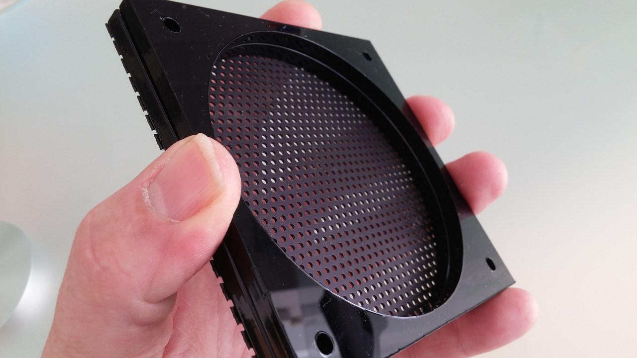
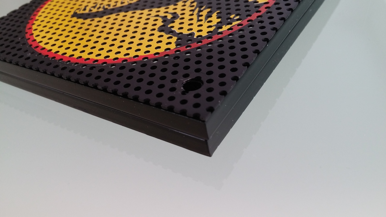
Newest project is a speaker light kit for my new Jurassic Park pinball machine. Inspired from what is available in various pinball shop I thought this can be done better. Lets use these programmable RGB leds based on a 2812 controller chip on each led to have various light effects.
First step
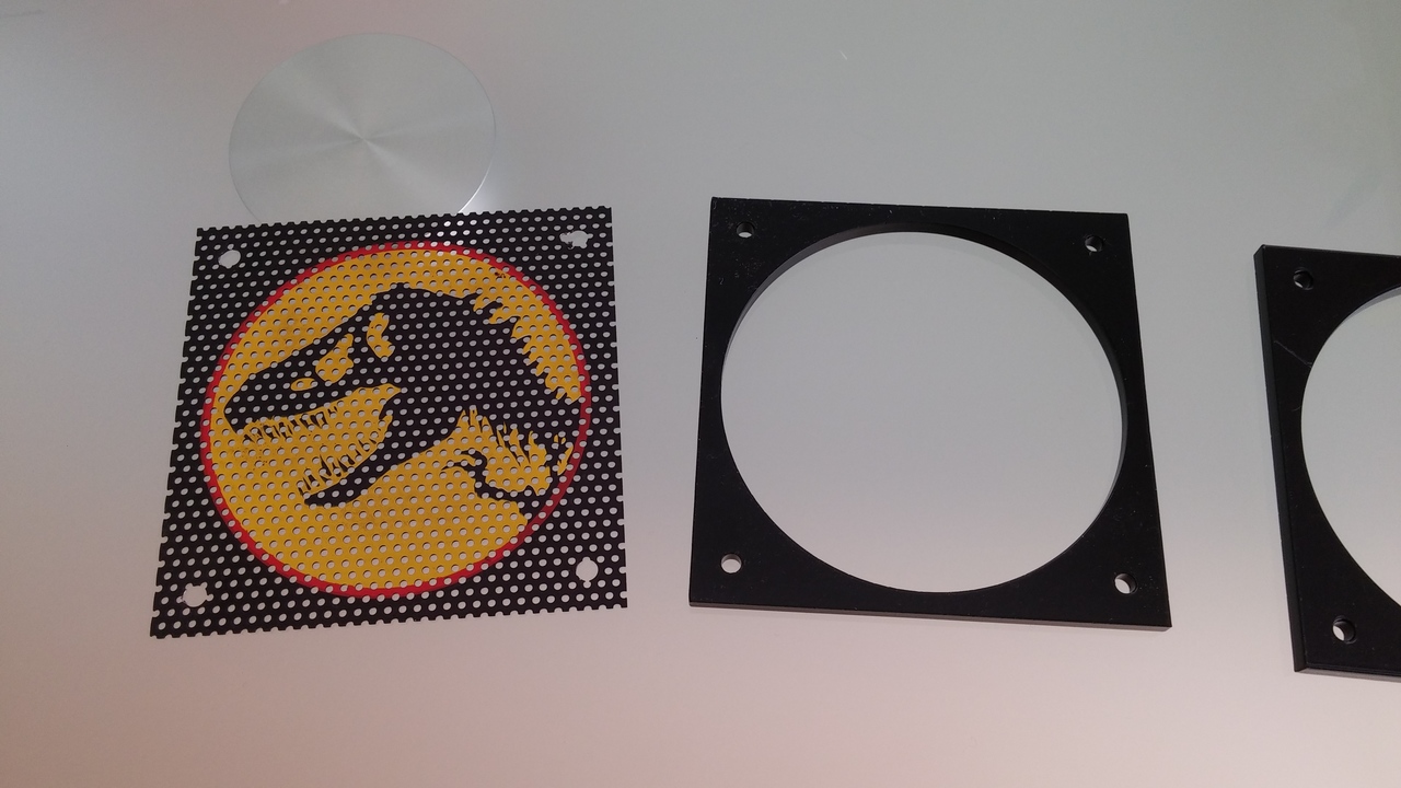
First step was to make room for a 2812 rgb led strip. Its 10mm wide so I ordered acrylic frames from my favorite laser cutter service based on the pdf attached to this article. The diameter is 92mm so it fits perfectly to data east speaker panels but maybe to wpc as well (I have to measure those). I used 4 of these frame in total each 5mm thick so two of them
speaker shade from jp and two acrylic frames
make up the right thickness to put a led strip inside.
two frame together to have room for one strip
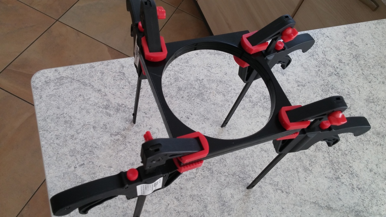
Second step
For better stability I glue them together in the right position.
glue the two frames together
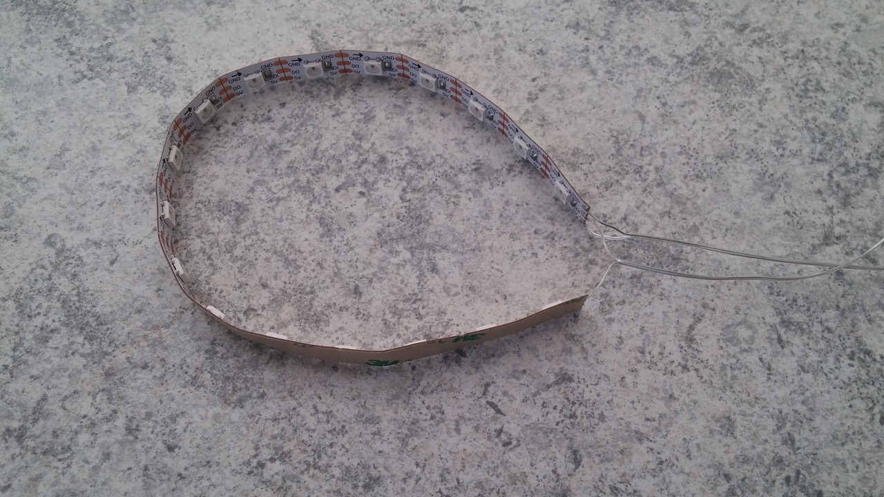
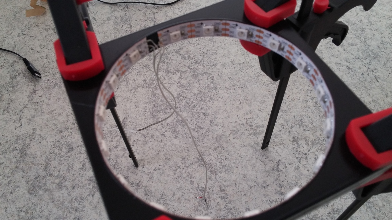
Cut the rgb strip after 17 leds which fills the circle almost complete.
Installing leds
Before putting it into the frame solder some wires to the strip, two for power supply, and two for data in and data out. Data out is needed as we are usually need two of these kits each for one speaker and we will simply chain them together.
The strips I used are self-adhesive so its easy to install the strip inside the frames.
As controller for the first proto type I used an arduino. This is the first impression.
Stay tuned for the final installment in my Jurassic Park.
First installment in my JP
Today I finished the first installment in my JP. Controller is not finished yet, jut runs a color cycle sequence, but more will come.
Mein neustes Projekt ist die Verwendung von LED Screen Panels als Displayersatz für echte DMD Panels in Flippern.
LED Panels sind in alle möglichen Grössen verfügbar die kleinesten mit Pixel Pitch von 2,5 mm was bei eine Auflösung von 128×32 Pixel ziemlich genau der Größe eines klassischen DMDs entspricht. Beim Lesen im Flippermarkt Forum bin ich auf ein Projekt gestossen, welches sich mit diesen RGB Panels beschäftigt, um sie in einem virtuellen Flipper zu verwenden: //www.flippermarkt.de/community/forum/showthread.php?t=160762
Zufällig wohnt der Autor „Lucky1“ grade bei mir um die Ecke und so entstand nach einem ersten Treffen schnell eine gemeinsame Initiative. Ziel für mich war es in erster Linie ein farbiges DMD in einem normalen Flipper einsetzen zu können. Einmal als Ersatz für ein defektes Vishay-DMD oder auch um den Pin aufzuwerten mit einer farbigen Anzeige.
Nachdem ich mit der RGB-General Illumination schon recht gute Erfahrungen gemacht hatte, war die nächste Idee auch die Flipperfinger selbst mit 2812 RGB Leds zu beleuchten.
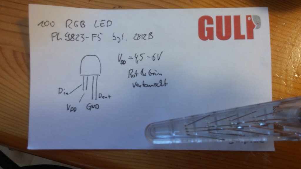
Transparente Flipperfinger gibt es bei BestOfPinball zu kaufen, also schnell bestellt und mit 5mm LED bestückt. Die LEDs bekommt man im 100er Pack bei Ebay.
Hier zunächst das Anschluss-Schema, die beiden langen Anschlüsse sind DataOut und Masse. An der Seite mit den langen Anschlüssen ist auch das Gehäuse etwas abgeflacht.
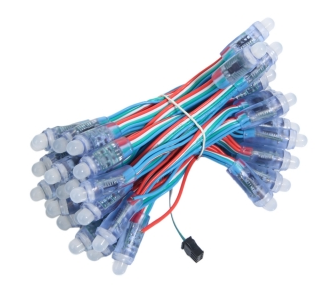
Einer meiner neusten Ideen war es die general Illumination (GI) eines Pins durch eine RGB-LED-Lichterkette zu ersetzen.
Diese RGB Lichterketten haben typischerweise 50 Stück 7mm LEDs mit integriertem WS2812 Controller und sind für wenig Geld bei Ebay oder beim China-Store Deiner Wahl zu finden.
Die einzelnen LEDs sind über einen 3 Draht Bus verbunden und unten vergossen. Der 3 Draht Bus besteht aus +5V, Masse und Data-In bzw. Out. Die LEDs sind werden einfach aneinander gereiht, wobei immer DataOut der einen LED mit dem DataIn der nächsten verbunden ist.
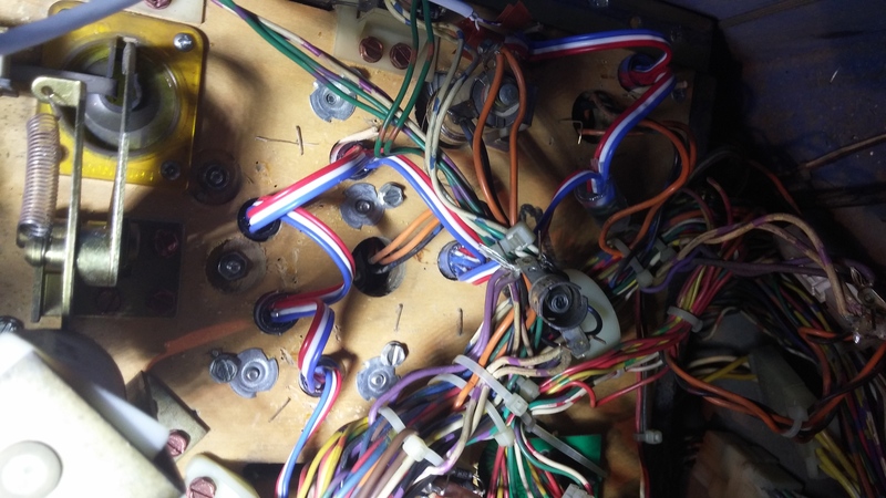
Von den Abmessungen passen die LEDs mit Gehäuse fast perfekt in der Löcher des Playfields wo bisher die GI-Fassungen angeschraubt oder festgetackert sind.
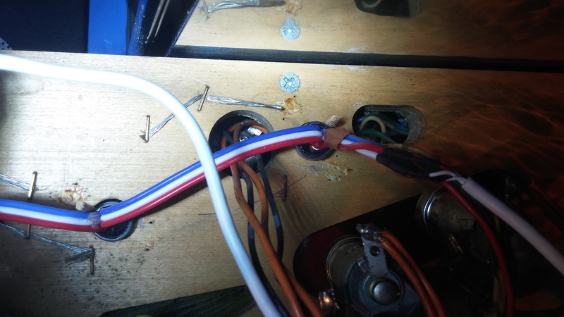
Bei Lampen die nahe genug beieinander liegen, können die LEDs direkt eingesetzt werden. Lampen, die weiter von einander entfernt sind, brauchen eine „Verlängerung“ des 3 Draht Busses. Hierzu wird die 3 Draht Verbindung aufgetrennt und ein 3 Draht Litzenelement
passender Länge eingesetzt. Dabei muss immer auf die „Richtung“ von DataIn -> DataOut geachtet werden. Was bei der ersten LED als DataOut rauskommt, geht bei der nächsten als DataIn wieder rein.
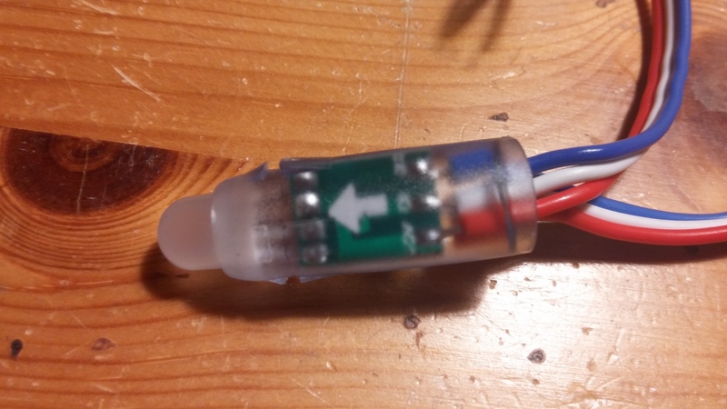
Von dieser Seite ist der weisse Anschluss DataIn erkennbar am weissen Pfeil. Auf der anderen Seite gehts mit DataOut wieder weiter.
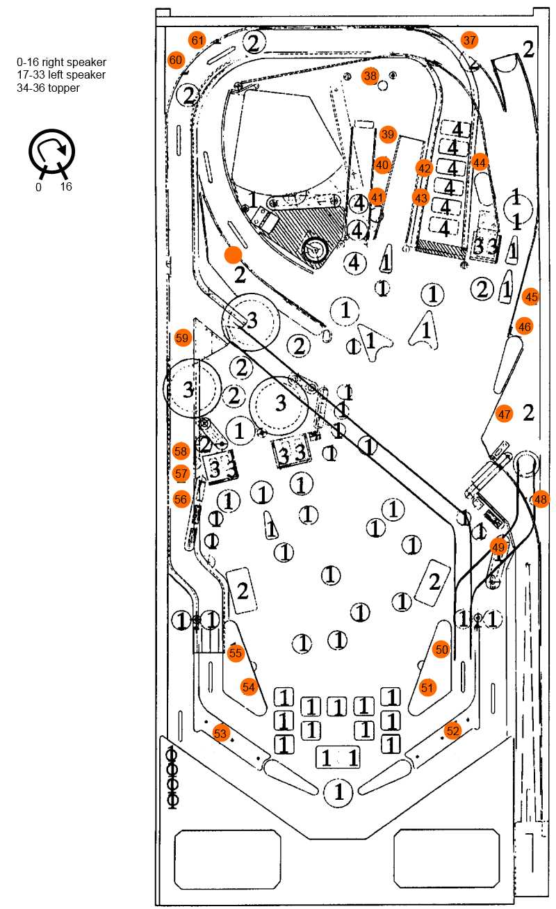
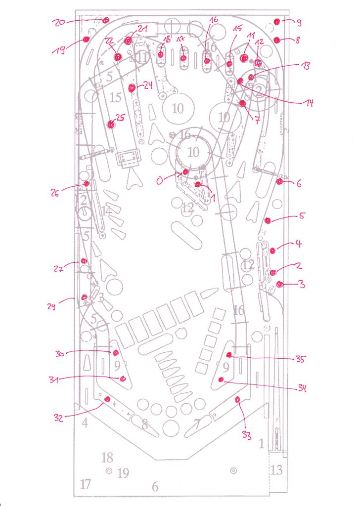
Es empfiehlt sich die LED-Kette in einem Kreis aussen herum anzuordnen beispielsweise beginnend vom linken Slingshot links nach oben, oben herum und dann auf der rechten Seite bis zum rechten Slingshot wieder herunter.
Mit dieser Anordnung sind Farbwechsel, die herumwandern ohne extra Aufwand in der Software zu realisieren. Anmerkung: der aktuelle Software-Stand sieht sowieso noch ein Mapping des Lampen-Index vor, so dass die Anordnung auf dem Playfield völlig unabhängig ist, von den Effekten die man haben möchte. Schlussfolgerung ist also man sollte die Anordnung so wählen, dass es für die Montage unter dem Playfield möglichst problemlos ist, muss dann aber ggf. das Mapping anpassen.
Am besten zeichnet mal einen Plan des Playfields (oder kopiert einen aus dem Manual) und zeichnet durch die nummerierten LEDs ein. (siehe unten)
Für die Stromversorgung empfehle ich ein separates 5V Netzteil mit 4-6A wie es sie für wenig Geld im Handel gibt. Am günstigsten sind Steckernetzteile mit 4A z.B. von Pollin, die bereits für weniger als 10 € zu haben sind. Angeschlossen werden diese Steckernetzteile über einen Mehrfachstecker, der zusammen mit dem Flipper eingeschaltet wird, oder – wenn man es professioneller mag – über eine zusätzliche Netzkupplung oder Netzstecker, der zusammen mit dem Hauptschalter des Flipper ein- und ausgeschaltet wird. Ausserdem haben diese Netzteil auch gleich den richtigen Anschluss für den Arduino.
Eine ersten Eindruck wie die LEDs wirken, sieht man in dem Video.
Hier wird aber zunächst mal nur eine sich wiederholende „Lightshow“ abgespult, die nicht in irgendeiner Form mit dem Spielgeschehen zu tun hat. Hierzu muss zusätzlicher „Input“ vom Pin geholt und die Software entsprechend angepasst werden.
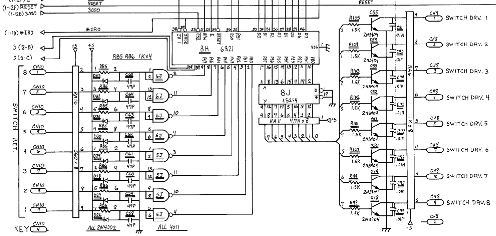
Wie man sieht arbeitet der Column Driver with +5V als inactive Potential durch den Pullup von 1K an +5V. Bei Aktivierung der Spalte schaltet der Spalten-Transistor nach Masse durch (active low pulse).
Angesteuert wird der Spalten-Transistor durch den 6821 PIA und den LS244 Treiber.
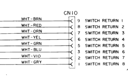
Ist ein Schalter aktiviert (geschlossen), dann kommt für diesen Schalter der LOW-Impuls auf der entsprechenden Row bei Switch Return wieder an, werden von den 4011er verstärkt, invertiert und über den B-Port des 6821 wieder gelesen.
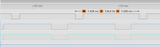
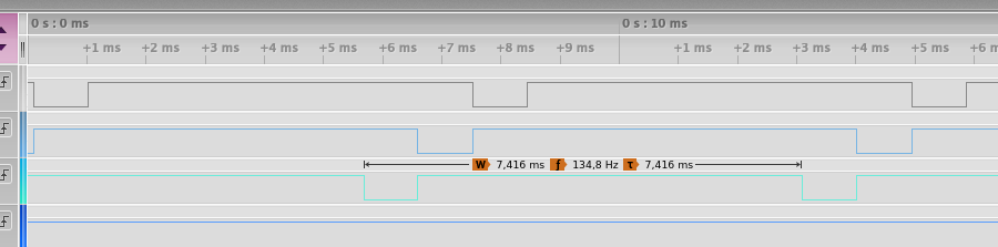
Timing
Der LOW-Impuls vom Column Strobe ist knapp ms lang dann kommen ca 6ms Pause und dann wiederholt sich das ganze.
Die Switch-Matrix wird also mit einer Frequenz von 135Hz abgefragt.
Um das nun mit dem Arduino sauber mit zu bekommen, brauchen wir einen Interrupt, der mit dem ersten Col-Strobe getriggert und damit syncronisiert wird.
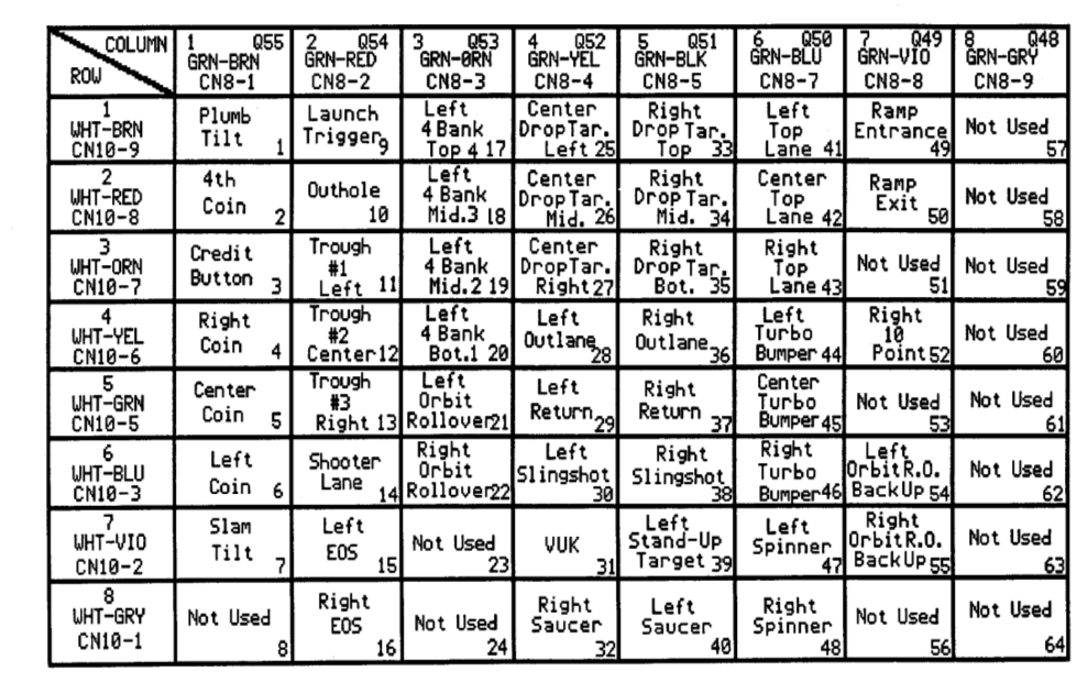
Nummern der Switches
Das Testprogramm zählt Spalten ab 0 daher sind die Indices im Programm immer eins weniger.
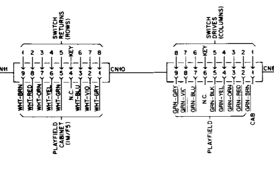
Auf Grund der Verkabelung sind die Rows ebenfalls vertauscht: (Notation ColRow Manual → ColRow Arduino) am Beispiel von Col2
Name
ColRow
ColRow
Name
ColRow
ColRow
LauchTrigger
21
11
Trough#3
25
15
Outhole
22
13
ShooterLane
26
12
Trough#1
23
10
Left Flipper
27
14
Trough#2
24
17
Right Flipper
28
16
Ansteuerung des Arduino
Basierend auf dem Timing von oben wurde folgendes Testprogramm entworfen: der Col-Strobe1 triggert den Interrupt 0 auf Pin2, dann wird ein Timer gestartet, der genau die gleiche Frequenz hat wir der Abfrage Takt der Col-Strobes. Bei jedem Timer-Interrupt wird dann das Row-Register PORTA beim Mega gelesen und in eine byte Matrix geschrieben.
Jetzt kann man einfache SwitchHandler auf einen bestimmten Schalter registrieren und daraus Aktionen ableiten. z.B. die Bälle in der Ball Truhe zählen → 3 Bälle länger als 5 Sekunden → Game over / Attract Mode, kein Ball drin → Multiball-Spiel.
Plan der GI-Lampen
Beim Erstellen des Programms muß man natürlich wissen, welche Lampe wo ist. Dafür hab ich ein kleines Testprogramm geschrieben welches die Lampen einzeln auf Tastendruck einschaltet und die Position auf der seriellen Schnittstelle ausgibt. Damit lässt sich folgender Plan erstellen:
Firmware
Die Software für den Controller findet sich auf Github. Der Aufbau der Software sieht ungefähr so aus:
Verwendete Libraries
Zum Ansteuern der LEDs wird FastLED genutzt, eingebettet in die Klasse LEDDriver. Diese Klasse beherbergt die LED Kette und steuert die Farben mit Hilfe von Effekten.
Klassen
Ein Effekt (Klasse) kennt eine Liste von LED Nummern (oder Indices) für die der Effekt gilt, hat eine Prio und einen Callback „updateLEDs()“ der die Farben der LEDs setzt. Hintergrund-Effekte haben die Prio 0, Effekte mit grösserer Prio übersteuern die mit kleineren Prio. Dies kann man nutzen, um bestimmte LEDs aufblitzen zu lassen.
Effekte werde beim LEDDriver registiert, damit der Driver die Callbacks auch aufrufen kann.
Zentrales Element der Steuerung ist der SwitchScanner. Diese Klasse kennt ständig den Zustand alle Switches mit und kann SwitchActions aufrufen. Eine SwitchAction registiert sich beim SwitchScanner unter Angabe des Switches bei dem Action „gezündet“ werden soll. Ausserdem kann man wählen, ob man regelmässig gerufen werden will oder nur wenn der Switch sich ändert.
Mit dem regelmässigen Rufen überwacht man den Ball-Speicher und weiss dann immer, wieviele Bälle im Speicher liegen.
Abhängig davon werden drei Hintergrund-Effekte aktiviert oder deaktiviert: Attract, NormalPlay und MultiBallPlay. Alle drei Effekte blenden unterschiedliche Paleletten hin und her. Attrach ziemlich bunt mit einer Mischung von Paletten, NormalPlay nur in Rot und Blau und MultiBall blinkt in Weiss.
Daneben sind noch weitere Effekte mit Prio 1 integriert: Flash, ein Effekt der ein bestimmte Farbe für die definierten LEDs für ein bestimmte Zeit übersteuert. Damit leuchten jedes Mal wenn der Ball an die Slings geht die passenden LEDs auf.
Von diesen Effekten lassen sich sehr einfach auch noch andere Sachen realisieren.
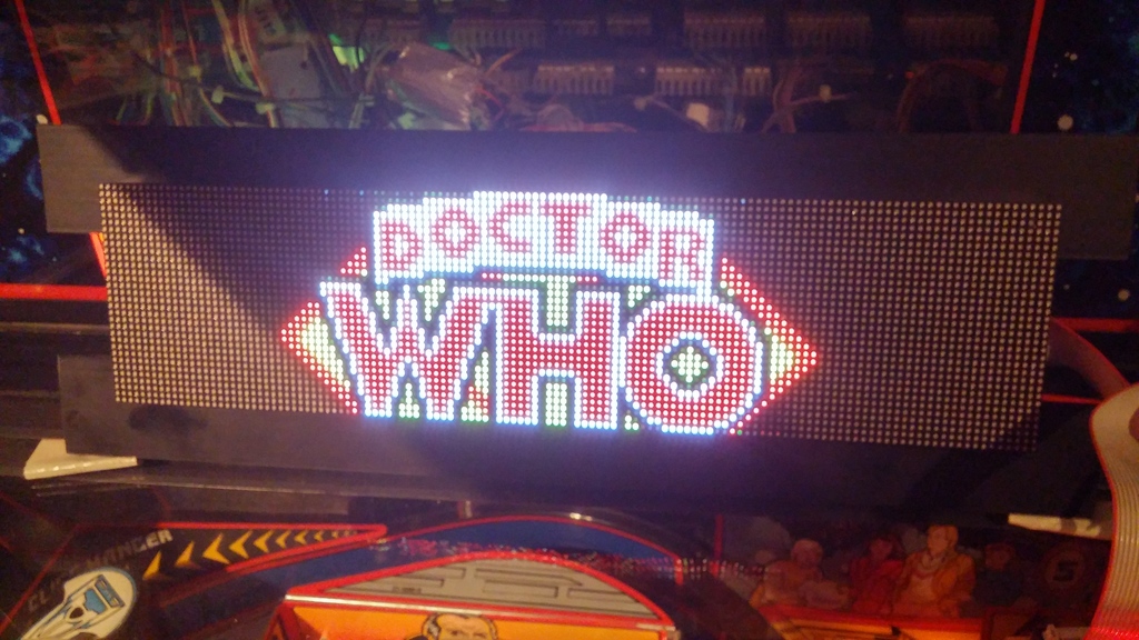
Und so sieht’s dann aus …
Video Qualität ist noch suboptimal.
Controller einbauen
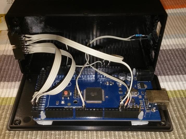
Die hier vorgeschlagene Lösung kommt völlig ohne zusätzliche Beschaltung allein mit einem Arduino Mega aus, d.h. es ist nur die Arduino in eine Gehäuse zu bauen.
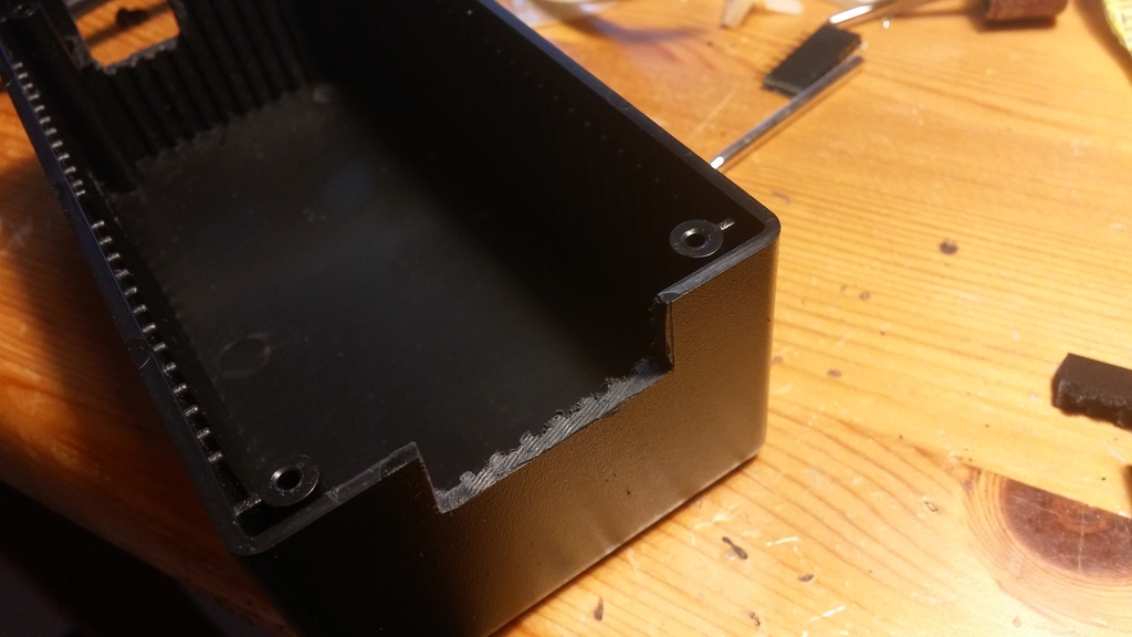
Hierzu verwendet man z.B. ein einfaches ABS Gehäuse und setzt den Arduino auf Platinen-Abstandshalter auf die Grundplatte.
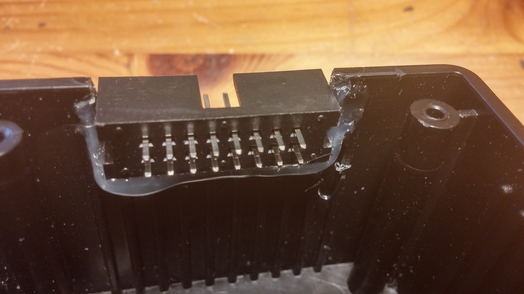
Für die Anschlüsse werden in den weichen Kunststoff ohne viel Mühe die passenden Ausschnitte geschnitten. Power-Anschluss und USB Stecker auf der einen Seite und einen Platinen Stecker für ein Flachbandkabel auf der anderen Seite. Der Platinen-Stecker wird in den Ausschnitt im Gehäuse einfach eingeklebt.
Anschliessend wird der Stecker nach innen verkabelt, um die Verbindung zum Arduino herzustellen. Für die Anschlüsse zur DataEast-CPU wird ein Adapter-Kabel benötigt, um die Signale für Column-Strobe und Row-Return abzugreifen. Ausserdem sind die Signale zum Ansteuern der RGB-LEDs nach aussen geführt.
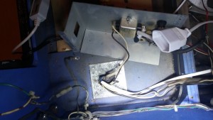
Das letzte Bild zeigt das bereits komplett verbundene Innere. Dort sind alle Verbindungen des Platinen-Steckers mit dem Arduino verbunden.
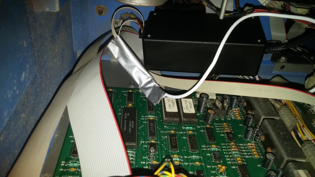
Einbau
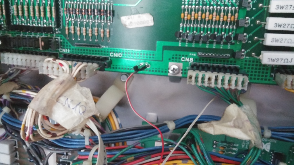
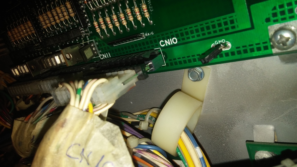
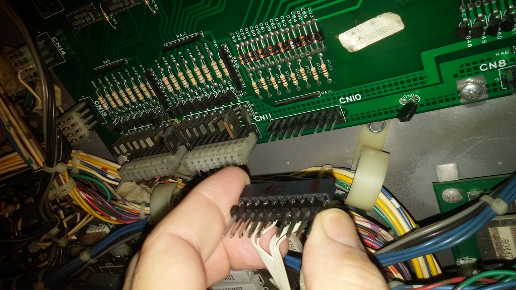
Die folgenden Bilder zeigen, wie der Anschluss in der Backbox erfolgt. Das Adapterkabel wird einfach per Zwischenstecker an CN10 bzw. CN8 angeschlossen, um so alle Signale für die Switch-Matrix abzugreifen. Zusätzlich wird noch ein Masse-Anschluss gebraucht.
Die Stromversorgung mit einem getrennten 5V – 4A Netzteil und die Zuleitung der RGB LEDs vom Playfield kommen von unten aus dem Cabinet und werden einfach eingesteckt.
Für ca. 60€ Material-Kosten ist der Umbau also zu haben. Was man wie immer nicht einrechnen darf, ist der Zeitaufwand 🙂
Was ist noch zu tun …
Die Software wird noch etwas optimiert oder ausgebaut:
Konfiguration per Flipper-Buttons für verschiedene „Light-Modes“
Und wer Lust hat, kann das ja nach bauen. Bei der Software Anpassung auf ein anderes Flippermodell bin ich gerne behilflich.
Ein weiteres Video hier:
Bitte beachten
Bei den Arbeiten an Flippern ist Vorsicht angebracht, bitte bei Arbeiten an den Geräten immer vorher den Stecker ziehen. Unterm Playfield gibt’s im eingeschalteten Zustand hohe Spannungen und ganz schnell hat man einen Kurzschluss fabriziert.
Im Zusammenhang mit dem Arduino muss man beachten, dass die Stromversorgung des Arduinos / der LED-Strips immer eingeschaltet sein muss, bevor man die USB Port zum Programmieren verbindet. Ansonsten ziehen die LED viel Strom über den USB Port und es kann irgendwas kaputt gehen, im schlimmsten Fall womöglich der USB Port des Computers. Alternativ kann man natürlich auf die LEDs zum Programmieren abtrennen.
We use cookies to ensure that we give you the best experience on our website. If you continue to use this site we will assume that you are happy with it.
Um unsere Webseite für Sie optimal zu gestalten und fortlaufend verbessern zu können, verwenden wir Cookies. Durch die weitere Nutzung der Webseite stimmen Sie der Verwendung von Cookies zu.OkRead more

 or any kind of disturbance I’m using a separate PSU 12V/5A only for the amplifiers. Connections between sound card output and amplifiers input uses shielded cables, also to minimize noise. For the backbox channel I simple combine the two stereo channels (left and right) to one with two resistors.
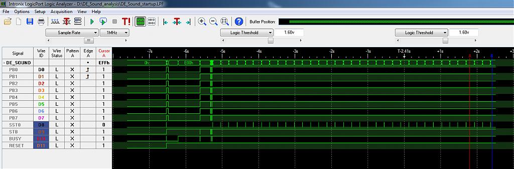
 den diese Steckernetzteile über einen Mehrfachstecker, der zusammen mit dem Flipper eingeschaltet wird, oder – wenn man es professioneller mag – über eine zusätzliche Netzkupplung oder Netzstecker, der zusammen mit dem Hauptschalter des Flipper ein- und ausgeschaltet wird. Ausserdem haben diese Netzteil auch gleich den richtigen Anschluss für den Arduino.
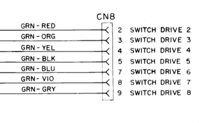